| Manassas Gap Railroad Engineering |
|
by Debbie Robison December 2002 |
|
|
|
By the time the Manassas Gap Railroad was built in the
1850s, engineering concepts had been developed for the construction of
railroads. Mathematical theory was applied to most aspects of roadbed,
embankment, and culvert design. Information contained in this article regarding actual construction of the Manassas Gap Railroad
pertains to culverts and embankments in Annandale, Virginia. |
| RAILROAD AND EMBANKMENT ENGINEERING |
|
Engineering calculations to determine the steepest railroad
roadbed grade were based on economics, rather than mere practicality. Engineers
felt that a train could pull fewer tons of goods up a slope towards market. It
was originally believed that heavier grades had a proportionately greater
impact on the weight a freight train could pull; however, by 1871, engineers
determined that heavier grades were less injurious since so much of a greater
ascent was required to double resistance. (Resistance was a primary factor in
the equation used to calculate required locomotive power.) In consequence of the engineering theory of
the day; however, Manassas Gap Railroad engineers designed roadbeds with
minimal slope by choosing a flat route, when possible, and both trenching
though hillsides and building up embankments. Construction costs were greater
on the sections of railway that required excavations and embankments.
Historically, engineers attempted to minimize costs by utilizing excess
excavated terrain, called “surplus”, in nearby embankments. If an embankment
was not being built within a short distance, the surplus was deposited on
nearby land in mounds called “spoil-banks”. When an embankment was constructed
and there was no surplus available, the deficiency was called “wantage”. The
required terrain was then obtained from “side-cuttings”. (Several probable
side-cutting sites were located within the Manassas Gap Railroad Historic
Site.) The excavation of earth was facilitated by the use of picks, ploughs,
scrapers, and spades to loosen the earth prior to shoveling the dirt and rocks
into wheelbarrows and horse-drawn carts. Steam-powered machines were also used
at this time for excavation and could dig and load 1,000 cubic yards of earth
per day. Where wheelbarrows were utilized, planks were laid in a path from the
side-cutting or excavation area to an off-loading area. It was recommended that
the slope leaving a side-cutting site not exceed 1 in 12. Generally speaking, once a route was
established, the boundaries of the roadbed were staked. Specifications may have
been provided requiring the area be cleared of “all trees, logs, brush, and
other vegetable matter.” All stumps and roots should then have been grubbed
out, followed by the removal of two feet of topsoil. Precautions were necessary in
constructing embankments to ensure they would not slip due to both their size
and the vibrations engendered by passing trains. The ideal method, albeit more
costly in time and expense, of building embankments was to form the embankment
in layers, or courses, not to exceed three or four feet thick. (This method was
especially recommended around masonry.) Vehicles used to convey the material
were required to drive over each successive layer to compress the soil.
Sometimes engineers found it advantageous to have the soil rammed. Ideally, the
layers were deposited in a concave fashion, thus reducing the likelihood the
soil would slip down the side slope. One practice used for reducing this slip
was to initially form the embankment wider at the top and narrower at the
bottom. The outside edges of the embankment were formed first; then the center
was gradually filled so that the earth had a tendency to move towards the
middle of the embankment. Finally, the excess earth at the top of the
embankment, as a result of forming the embankment wider at the top, was thrown
down the slope to fill in the narrow bottom portion of the embankment. During
construction, a trench may have been built at the foot, or “toe”, of an
embankment to reduce the tendency of the embankment to spread. Engineers
designed the side slope of embankments based upon the type of soil
utilized. It was believed that common
earth would stand on a 1 to 1 (45 degree) slope,
though a 1-1/2 to 1 (33 degree) slope
was preferred, especially for high embankments. (A 33 degree slope was
achieved for the Manassas Gap Railroad Historic Site embankment, which is
composed of silty, slightly micaceous fine sand and rock.) Gravel and high-clay
soils required shallower slopes. Slopes for excavations were recommended at 2
to 1 to allow sun and wind to reach the roadbed to keep it dry. The predominant embankment
construction method involved building up the embankment to its full height at
one end and continuing the roadbed by transporting wagonloads of earth
(containing about three cubic yards) atop the embankment along temporary rails
to its current terminus where it was dumped. It was a recommended practice to
seed the side-slopes of both embankments and excavations to stabilize those
areas. The top of embankments and the bottom
of excavations were brought to a height two feet below the intended finished
height, or "formation level", though allowances were made for
settling, or “shrinkage”, of embankments. The surface was shaped with a crown
at the middle with a falloff to the sides, similar to road construction, to
allow water runoff. Ballast, composed of gravel, broken stones, or quarry
rubbish, was set atop the formation level to spread the bearing of the sleepers
over a large surface of ground, keep the track in place, secure drainage, and
give medium elasticity. The term ballast was derived from the original use of
ships' ballast. The ballast was laid on rock as well as earth and, if properly
placed, extended the full width of the top of the embankment. Recent inspection
of the embankment that passes through the Manassas Gap Railroad Historic Site
does not reveal the presence of ballast. Either the embankment only reached the
formation level when construction of the Independent Line ceased in 1857, or
the Manassas Gap Railroad Company intended to lay the rail directly on plain
roadbed. Company records indicate that rail was laid on both ballast and plain
roadbed. The width of the roadbed included the
distance between the rails and an area on each side of the rails, called
“side-spaces”, used in the event of train derailment. The side-space widths
were from 5 to 8 feet for different railways. High embankments were given wider
side-spaces. The design width of a roadbed was determined by adding the width
between the rails to the side-space widths.
The gauge on |
| CULVERT ENGINEERING |
|
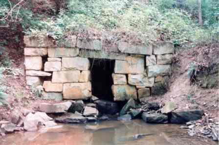
The culvert foundations were made of
large 18" to 22" quarried micaceous gneiss blocks. Engineers were
aware in the mid-nineteenth century that ineffective culvert foundations caused
the superstructure to sink into the soil below, especially under the middle of
the embankment. The foundation and flooring stones were sloped to facilitate
water drainage. A slope of 1” for every 10’ was desired. At the Manassas Gap
Railroad Historic Site, a slope of approximately 7/8” in 10’ was achieved at
the western culvert and approximately 1-1/4” in 10’ at the eastern culvert. The culvert walls were made of stones,
approximately 36" to 40" thick, stacked on top of the foundation
stones in a straight line and plumb. As the culvert wall face stones were
stacked, large stones were set behind them. Smaller stones were used as fill to
level the back stones with the face stones. Once both walls of the culvert were
constructed to finished height, very large lintel stones were set over the walls
to span the culvert. These stones bear on both walls a minimum of 6" and
are from 12" to 20" thick. The lintels were most likely hewn by
sledge hammering a star bit to an average depth of 2-1/4” and boring additional
holes along a line spaced, on average, 6” apart. An alternative tool for
drilling holes was a long steel bar, chisel-edged, which was raised and let
fall on the desired point. At each stroke, the bar was partially turned so the
cuts crossed in a star pattern. Some masons inserted feathers, half-round metal
pieces, into the holes with wedges set in between. The wedges received even
pressure along the line to split the rock. Other masons dripped water onto
wooden dowels placed in the holes. Expansion cracked the stone. Explosives were
also employed to blow apart the rock. This “shot” stone typically contains
hairline cracks and is not ideal for masonry.
Historically, when soil conditions
were marshy or of "quicksand", foundations were laid on a 3' to 6'
thick bed of gravel, sand, or "stone broken to turnpike size." An
engineering text recommended the bed extend several feet beyond the masonry in
each direction and rammed to compact the fill. The gravel and sand were
thoroughly wet to aid in the consolidation. It was believed this foundation bed
was sufficient for a "moderate height embankment." When
masonry was laid on a smooth surface of rock or a platform of timbers, stone
pilings were driven in front of the masonry to prevent slippage. No evidence of
pilings was discovered at either of the Manassas Gap Railroad Historic Site
culverts; however, an apron, composed of stone rip rap, was placed adjacent to
the masonry to prevent undermining by scour. Sharp directional changes of Coon
Branch at the culvert outlets most likely caused foundation undermining as high
water exiting the culvert struck the opposite bank and caused the water to move
in a swirling motion back to the foundation. Each end of the culverts was secured
with large headwalls. These walls have finished faces, not polished, with
joints from 1/2" to 1" thick. The stones have cut corners, level
tops, and like the rest of the culvert masonry, were laid completely dry.
Portland cement was not available in the mid-Atlantic
region until 1872. The original builders would have concluded that a lime-based
mortar could not have withstood the effects of constant water erosion. Careful
examination of the masonry shows no evidence of mortar. Built properly, stone
walls have the ability to move water away from themselves and therefore do not
suffer the effects of a freeze/thaw cycle. The stone culverts and earthen
embankments at the Manassas Gap Railroad Historic Site were constructed using
generally accepted civil engineering practices of the mid-nineteenth century,
many of which continue to be used today. |
| BIBLIOGRAPHY |
|
Cochran, Allen. Telephone interview. 5 November 2002. Gilespie, William. M., LL.D., C.E. A Manual of the
Principles and Practice of Road-Making: Comprising the Location, Construction,
and Improvement of Roads: (Common, McAdam, Paved, Plank, Etc.) and Rail-Roads.,
Tenth edition, With Large Addenda. McD Goldsborough, John. Letter to the Secretary of the McRaven Charles. Stonework techniques and Projects. Trautwine, John C., The Civil Engineer’s Pocket-Book of
Mensuration, Trigonometry, Surveying, Hydraulics, Etc. Phil, Claxton,
Remsen, & Haffelfinger, 1874. |

 While Manassas Gap Railroad Chief
Engineer John McD. Goldsborough may have had confidence in his engineering
theory and practice, today we know with certainty that the culverts built by
the Manassas Gap Railroad Company have proven Goldsborough's ability by
standing the test of time.
While Manassas Gap Railroad Chief
Engineer John McD. Goldsborough may have had confidence in his engineering
theory and practice, today we know with certainty that the culverts built by
the Manassas Gap Railroad Company have proven Goldsborough's ability by
standing the test of time.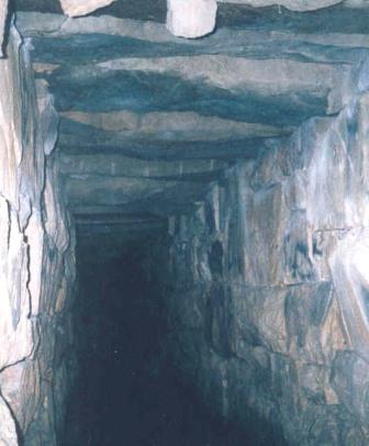 The lintels were shaped into an
elongated pentagon configuration with a triangular, roof-like peak. This
resulted in the bearing pressure of the embankment to be distributed over the
lintel, the back stones, and the fill stones in the same manner that an arch
bears weight. Evidence exists at the western inlet opening that small stones
were stacked in an arch-shaped manner over the culvert. This design, along with
the firm foundation, kept the embankment from pressing the side walls together,
a concern that nineteenth century engineers designed to overcome either by
using a large masonry foundation or an inverted brick arch flooring.
The lintels were shaped into an
elongated pentagon configuration with a triangular, roof-like peak. This
resulted in the bearing pressure of the embankment to be distributed over the
lintel, the back stones, and the fill stones in the same manner that an arch
bears weight. Evidence exists at the western inlet opening that small stones
were stacked in an arch-shaped manner over the culvert. This design, along with
the firm foundation, kept the embankment from pressing the side walls together,
a concern that nineteenth century engineers designed to overcome either by
using a large masonry foundation or an inverted brick arch flooring.